Tuesday, 8 January 2013

Final Code : MMC SD Card interfacing

Final Code : MMC SD Card interfacing


►Final Code

Using these functions, along with Chan’s tff.c module creates all the tools you need to read and write to a FAT16 SD card. An example program to display the root directory of the SD card would look like this:

CODE:
#include "integer.h"
#include "tff.h"
#include "diskio.h"

FATFS SDCard;

void ShowDirectory( char *path );
char *ShowFatTime( WORD ThisTime );
char *ShowFatDate( WORD ThisDate );
DWORD get_fattime();

void main()
{
   /* 1) mount drive... */
   if( f_mount( 0, &SDCard ) )
   {
      printf("Couldn't mount drive...\r\n");
      while( 1 );
   }

   /* 2) initialize card... */
   if( disk_initialize( 0 ) & STA_NOINIT )
   {
      switch( CardType )
      {
         case 0 :
            printf("Couldn't find SD card\r\n");
            break;
         case 1 :
            printf("Card type is MMC - Can't use this type\r\n");
            break;
         case 2 :
            printf("Couldn't initialize SD Card drive...\r\n");
            break;
         default :
            printf("Unknown Card Type error...\r\n");
            break;
      }
      while( 1 );
   }

   /* 3) show directory... */
   ShowDirectory("");

   while( 1 );
}

void ShowDirectory( char *path )
{
   FILINFO finfo;
   DIR dirs;
   FATFS *fs;
   DWORD clust;
   ULONG TotalSpace, FreeSpace;
   FRESULT res;
   char VolumeLabel[12];

   if(disk_read(0, SDCard.win, SDCard.dirbase, 1) != RES_OK)
   {
      printf("\r\nCouldn't read directory sector...\r\n");
      return;
   }

   strncpy( VolumeLabel, &SDCard.win, 11 );
   VolumeLabel[ 11 ] = 0x00;
   if( f_opendir(&dirs, path) == FR_OK )
   {
      if( VolumeLabel[0] == ' ' )
         printf("\r\n Volume in Drive C has no label.\r\n");
      else
         printf("\r\n Volume in Drive C %s\r\n", VolumeLabel );
      printf(" Directory of C:\%s\r\n\n", path );
      while( (f_readdir(&dirs, &finfo) == FR_OK) && finfo.fname[0] )
      {
         putchar('[');
         putchar(( finfo.fattrib & AM_RDO ) ? 'r' : '.');
         putchar(( finfo.fattrib & AM_HID ) ? 'h' : '.');
         putchar(( finfo.fattrib & AM_SYS ) ? 's' : '.');
         putchar(( finfo.fattrib & AM_VOL ) ? 'v' : '.');
         putchar(( finfo.fattrib & AM_LFN ) ? 'l' : '.');
         putchar(( finfo.fattrib & AM_DIR ) ? 'd' : '.');
         putchar(( finfo.fattrib & AM_ARC ) ? 'a' : '.');
         putchar(']');

         printf(" %s  %s   ",
            ShowFatDate(finfo.fdate), ShowFatTime( finfo.ftime ));
         printf("%s %6ld %s\r\n", (finfo.fattrib & AM_DIR)?"<DIR>":"     ",
            finfo.fsize, finfo.fname );
      }
   }
   else
   {
      printf("The system cannot find the path specified.\r\n");
      return;
   }

   printf("%cCalculating disk space...\r", 0x09 );

   // Get free clusters
   res = f_getfree("", &clust, &fs);
   if( res )
   {
      printf("
f_getfree() failed...\r\n"
);
      return;
   }

   TotalSpace = (DWORD)(fs->max_clust - 2) * fs->csize / 2;
   FreeSpace = clust * fs->csize / 2;
   printf("%c%lu KB total disk space.\r\n", 0x09, TotalSpace );
   printf("%c%lu KB available on the disk.\r\n", 0x09, FreeSpace );
}

char *ShowFatTime( WORD ThisTime )
{
   char msg[12];
   BYTE AM = 1;

   int Hour, Minute, Second;

   Hour = ThisTime >> 11;        // bits 15 through 11 hold Hour...
   Minute = ThisTime & 0x07E0;   // bits 10 through 5 hold Minute... 0000 0111 1110 0000
   Minute = Minute >> 5;
   Second = ThisTime & 0x001F;   //bits 4 through 0 hold Second...   0000 0000 0001 1111
 
   if( Hour > 11 )
   {
      AM = 0;
      if( Hour > 12 )
         Hour -= 12;
   }
   
   sprintf( msg, "%02d:%02d:%02d %s", Hour, Minute, Second*2,
         (AM)?"AM":"PM");
   return( msg );
}


char *ShowFatDate( WORD ThisDate )
{
   char msg[10];

   int Year, Month, Day;

   Year = ThisDate >> 9;         // bits 15 through 9 hold year...
   Month = ThisDate & 0x01E0;    // bits 8 through 5 hold month... 0000 0001 1110 0000
   Month = Month >> 5;
   Day = ThisDate & 0x001F;      //bits 4 through 0 hold day...    0000 0000 0001 1111
   sprintf( msg, "%02d/%02d/%02d", Month, Day, Year-20);
   return( msg );
}

DWORD get_fattime()
{
   RTC_CURRENT rtc;
   RTC_read( &rtc );
 
   return         ((DWORD)((WORD)(rtc.Year) + 20) << 25)
                  | ((DWORD)rtc.Month << 21)
                  | ((DWORD)rtc.Date << 16)
                  | ((DWORD)rtc.Hours << 11)
                  | ((DWORD)rtc.Minutes << 5)
                  | ((DWORD)rtc.Seconds >> 1);
}
 

Disk IO functions : MMC SD Card interfacing

Disk IO functions : MMC SD Card interfacing

►Disk related functions

The only file you need to modify is diskio.c, and the functions within it. This module is the interface for Chan’s library to your SD card. If the functions within this file are written as wrappers to your fundamental functions, Chan’s library will work without any problems.

The functions in this module are as follows: disk_initialize, disk_status, disk_read, disk_write, and disk_ioctl. Also note that the only feature within disk_ioctl that is used is CTRL_SYNC. These functions, along with all of the previous functions, will do the job.

CODE:
DSTATUS disk_initialize( BYTE drv )
{
   /* Supports only single drive */
   if( drv != 0)
      return STA_NOINIT;
 
   /* if initialization succeeds... */
   if( !SD_Init() )
   {
      /* Clear STA_NOINIT */
      Stat &= ~STA_NOINIT;
   }
 
   /* return current status */
   return( Stat );
}

DSTATUS disk_status( BYTE drv   )
{
   /* Supports only single drive */
   if( drv != 0)
      return STA_NOINIT;

   /* return current status */
   return( Stat );
}

DRESULT disk_read ( BYTE drv, BYTE *buff, DWORD sector, BYTE count )
{
   /* Supports only single drive and must have a size of 1 sector */
   if( drv || !count || (count>1) )
      return( RES_PARERR );

   /* if we haven't initialized the card yet... */
   if( Stat & STA_NOINIT )
      return( RES_NOTRDY );
 
   /* Single block read */
   if( SD_ReadSector( sector, buff ) )
      return( RES_ERROR );
 
   /* return successful result: OK */
   return( RES_OK );
}

#if _READONLY == 0
DRESULT disk_write( BYTE drv, const BYTE *buff, DWORD sector, BYTE count )
{
   /* Supports only single drive and must have a size of 1 sector */
   if( drv || !count || (count>1) )
      return( RES_PARERR );

   /* if we haven't initialized the card yet... */
   if( Stat & STA_NOINIT )
      return( RES_NOTRDY );
   
   /* Single block write */
   if( SD_WriteSector( sector, buff ) )
      return( RES_ERROR );
   
   /* return successful result: OK */
   return( RES_OK );
}
#endif // _READONLY

DRESULT disk_ioctl ( BYTE drv, BYTE ctrl, void *buff )
{
   DRESULT res;
   BYTE  *ptr = buff;

   /* Supports only single drive */
   if( drv != 0)
      return RES_PARERR;
 
   /* if we haven't initialized the card yet... */
   if( Stat & STA_NOINIT )
      return RES_NOTRDY;
 
   res = RES_ERROR;
 
   switch( ctrl )
   {
      /* Flush dirty buffer if present */
      case CTRL_SYNC :
         SPI_EnableCS();
         if( SD_WaitForReady() == 0xFF )
            res = RES_OK;
         break;
 
      default:
         res = RES_PARERR;
         break;
   }
 
   SPI_DisableCS();
   SPI_Byte( 0xFF );
   return res;
}
 

Reading and Writing a single sector : MMC SD Card interfacing

Reading and Writing a single sector : MMC SD Card interfacing

►Reading and Writing a single sector

Another fundamental function is reading a single sector of data from the SD card. Since the sector size is fixed in SPI mode, we expect to read 512 bytes at a time. The following function will achieve this.

A. Reading Sector

CODE:
BYTE SD_ReadSector( ULONG SectorNumber, BYTE *Buffer )
{
   BYTE c, i;
   WORD count;

   /* send block-read command... */
   SD_Command( CMD_READ_SINGLE_BLOCK, SectorNumber << 9 );
   c = SD_GetR1();
   i = SD_GetR1();
   count = 0xFFFF;
 
   /* wait for data token... */
   while( (i == 0xff) && --count)
      i = SD_GetR1();

   /* handle time out... */
   if(c || i != 0xFE)
      return( 1 );

   /* read the sector... */
   for( count=0; count<SD_DATA_SIZE; count++)    
      *Buffer++ = SPI_Byte(0xFF);
 
   /* ignore the checksum... */
   SPI_Byte(0xFF);        
   SPI_Byte(0xFF);
 
   /* release the CS line... */
   SPI_DisableCS();

   return( 0 );
}


B. Writing Sector

CODE:
BYTE SD_WriteSector( ULONG SectorNumber, BYTE *Buffer )
{
   BYTE i;
   WORD count;

   /* send block-write command... */
   SD_Command( CMD_WRITE_SINGLE_BLOCK, SectorNumber << 9 );
   i = SD_GetR1();

   /* send start block token... */
   SPI_Byte( 0xFE );

   /* write the sector... */
   for( count= 0; count< 512; count++ )
   {
      SPI_Byte(*Buffer++);
   }
   /* ignore the checksum (dummy write)... */
   SPI_Byte(0xFF);        
   SPI_Byte(0xFF);
 
   /* wait for response token... */
   while( SPI_Byte( 0xFF ) != 0xFF)
 
   /* these 8 clock cycles are critical for the card */
   /* to finish up whatever it's working on at the */
   /* time... (before CS is released!) */
   SPI_Byte( 0xFF );
 
   /* release the CS line... */
   SPI_DisableCS();
   SPI_Byte( 0xFF );
   return( 0 );
}


One final function

Finally, you will need one last function to emulate everything Chan’s library needs to talk to the SD card. This function is a simple flush function that is used to make sure the card is ready for the next command.

CODE:
BYTE SD_WaitForReady()
{
   BYTE i;
   WORD j;

   SPI_Byte( 0xFF );
 
   j = 500;
   do
   {
      i = SPI_Byte( 0xFF );
      Delay( 1 );
   } while ((i != 0xFF) && --j);
 
   return( i );
}
 

Global Type Difinition : MMC SD Card interfacing

Global Type Difinition : MMC SD Card interfacing


►Global type definitions and variables

Here are some standard definitions I use throughout this tutorial. You can modify them to suite your needs, but these seem to work fine for me. I modified the INTEGER.H file included in Chan’s library as follows:


CODE:
/*-------------------------------------------*/
/* Integer type definitions for FatFs module */
/*-------------------------------------------*/

#ifndef _INTEGER

   /* These types must be 16-bit, 32-bit or larger integer */
   typedef int                          INT;
   typedef unsigned int UINT;
 
   /* These types must be 8-bit integer */
   typedef signed char          CHAR;
   typedef unsigned char        UCHAR;
 
   /* These types must be 16-bit integer */
   typedef short                        SHORT;
   typedef unsigned short       USHORT;
 
   /* These types must be 32-bit integer */
   typedef long                 LONG;
   typedef unsigned long        DWORD;


   #ifndef STANDARD_TYPES
      #define STANDARD_TYPES
      typedef unsigned char BYTE;
      typedef unsigned int  WORD;
      typedef unsigned long ULONG;
   #endif

   /* Boolean type */
   typedef enum { FALSE = 0, TRUE } BOOL;
 
   #define _INTEGER
#endif


The following variable is global, and necessary for Chan’s Library

CODE:
xdata WORD CardType;    /* MMC = 0, SDCard v1 = 1, SDCard v2 = 2 */


These are specific to the SPI interface in my microcontroller. Again, you can modify them to suite your needs, and better match your hardware environment.
CODE:
enum SPI_FREQUENCIES { kHz400, MHz1, MHz5, MHz10 };
/* =========================================================== */
/* Table 59. SPICON0: Control Register 0                       */
/* (SFR D6h, Reset Value 00h)                                  */
/*                                                             */
/* BIT SYMBOL   R/W   DEFINITION                               */
/* --- ------   ---   ---------------------------------------- */
/*  7    --      -    Reserved...                              */
/*  6    TE     R/W   T)ransmitter E)nable                     */
/*                    0 = transmitter disabled,                */
/*                    1 = transmitter enabled                  */
/*  5    RE     R/W   R)eceiver E)nable                        */
/*                    0 = receiver disabled,                   */
/*                    1 = receiver enabled                     */
/*  4  SPIEN    R/W   SPI) E)nable                             */
/*                    0 = entire SPI interface disabled,       */
/*                    1 = entire SPI interface enabled         */
/*  3   SSEL    R/W   S)lave SEL)ection                        */
/*                    0 = SPISEL output always '1',            */
/*                    1 = SPISEL output '0' during transfers   */
/*  2   FLSB    R/W   F)irst LSB)                              */
/*                    0 = transfer MSB first,                  */
/*                    1 = transfer LSB first                   */
/*  1   SPO     R/W   S)ampling PO)larity                      */
/*                    0 = Sample transfer data at falling edge */
/*                        of clock (SPICLK is '0' when idle)   */
/*                    1 = Sample transfer data at rising edge  */
/*                        of clock (SPICLK is '1' when idle)   */
/*  0    --      -    Reserved...                              */
/*                                                             */
/* =========================================================== */
        #define TE     0x40
        #define RE     0x20
        #define SPIEN  0x10
        #define SSEL   0x08 // This feature is disabled in PDSoft...
        #define FLSB   0x04
        #define SPO    0x02
 

The following table is used for setting the frequency of the SPI clock – This is definitely hardware specific. My system’s normal crystal frequency is 40.0Mhz, but this example uses a 22.1184Mhz crystal, so that’s why I setup this table. Also, the upsd3334D microcontroller is a 4-clocker, not a 12-clocker device, which means it takes only 4 clock cycles to execute a simple instruction, not 12 like a typical 8052. Your hardware will dictate the values you use as timer constants.

CODE:
/* =========================================================== */
/* Table 61. SPICLKD: SPI Prescaler (Clock Divider)            */
/*           Register (SFR D2h, Reset Value 04h)               */
/*           based on frequency, the following are             */
/*           divisors for the SPI clock register               */
/* =========================================================== */

#define SPI_FREQUENCY_10MHz     4   // Fastest: 10MHz @ 40MHz, and
                                    // 5.529MHz at 22.1184MHz
#ifdef NORMAL_SPEED
   #define SPI_FREQUENCY_5MHz   8   // 5MHz
   #define SPI_FREQUENCY_1MHz   40  // 1MHz
   #define SPI_FREQUENCY_400KHz 100 // 400kHz
#else
   #define SPI_FREQUENCY_5MHz   4   // 5.529MHz
   #define SPI_FREQUENCY_1MHz   20  // 1.105MHz
   #define SPI_FREQUENCY_400KHz 56  // 394.971kHz
#endif

/* =========================================================== */
/* Table 62. SPISTAT: SPI Interface Status Register            */
/*                    (SFR D3h, Reset Value 02h)               */
/*                                                             */
/* BIT   SYMBOL   R/W   DEFINITION                             */
/* ---   ------   ---   -------------------------------------- */
/*  7      --      -    Reserved...                            */
/*  6      --      -    Reserved...                            */
/*  5      --      -    Reserved...                            */
/*  4     BUSY     R    SPI Busy                               */
/*                      0 = Transmit or Receive is completed   */
/*                      1 = Transmit or Receive is in process  */
/*  3     TEISF    R                                           */
/*        T)ransmission E)nd I)nterrupt S)ource F)lag          */
/*                      0 = Automatically resets to '0'        */
/*                          when firmware reads this register  */
/*                      1 = Automatically sets to '1'          */
/*                          when transmission end occurs       */
/*  2    RORISF    R                                           */
/*       R)eceive O)verrun I)nterrupt S)ource F)lag            */
/*                      0 = Automatically resets to '0'        */
/*                          when firmware reads this register  */
/*                      1 = Automatically sets to '1'          */
/*                          when receive overrun occurs        */
/*  1     TISF     R    T)ransmission I)nterrupt S)ource F)lag */
/*                      0 = Automatically resets to '0'        */
/*                          when SPITDR is full                */
/*                         (just after the SPITDR is written)  */
/*                      1 = Automatically sets to '1'          */
/*                          when SPITDR is empty               */
/* (just after BYTE loads from SPITDR into SPI shift register) */
/*  0     RISF     R    R)eception I)nterrupt S)ource F)lag    */
/*                      0 = Automatically resets to '0'        */
/*                          when SPIRDR is empty               */
/*                         (after the SPIRDR is read)          */
/*                      1 = Automatically sets to '1'          */
/*                          when SPIRDR is full                */
/*                                                             */
/* =========================================================== */
#define     BUSY              0x10
#define     TEISF             0x08
#define     RORISF            0x04
#define     TISF              0x02
#define     RISF              0x01
 

MMC SD Card Interfacing

SPI Port setup : MMC SD Card interfacing

►Setting up the SPI port during startup.A51


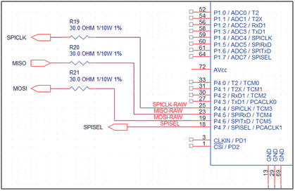
For the upsd3334D, the SFR’s that set the functional aspects for the SPI port are P4SFS0 and P4SFS1. Your microcontroller will vary here, but the main idea is to setup the SPI pins so that you have an M0SI, MISO, SPICLK, and CS – These names correspond to “Micro OUT Slave IN”, “Micro IN Slave OUT”, “SPI CLocK”, and “Chip Select” respectively.


For my microcontroller, I set the port for the following settings, from within the STARTUP.A51 file (in assembler):

CODE:

;------------------------------------------------------------;
; Program uPSD PORT-4 registers...                           ;
;                                                            ;
; P4SFS0 - sets the primary function of the pins             ;
; default is '0', which is GPIO pin                          ;
;                                                            ;
; 0 - buzzer output (PWM)   (set as alternate - 1)           ;
; 1 - SPIADDRESS SELECT 0 -|                                 ;
; 2 - SPIADDRESS SELECT 1  | These are used as 3-8           ;
;                            decoder for SPI device select   ;
; 3 - SPIADDRESS SELECT 2 -| (set as GPIO - 0)               ;
; 4 - spiclock               (set as alternate - 1)          ;
; 5 - MISO                   (set as alternate - 1)          ;
; 6 - MOSI                   (set as alternate - 1)          ;
; 7 - manual spi select line (set as GPIO - 0)               ;
;------------------------------------------------------------;
; P4SFS1 - sets the alternate function,                      ;
; if corresponding bit in P4SFS0 is set                      ;
;                                                            ;
; 0 - PCA0 Module 0, TCM0                (set as 0)          ;
; 1 - ignored, since P4SFS0 is 0 already (set as 0)          ;
; 2 - ignored, since P4SFS0 is 0 already (set as 0)          ;
; 3 - ignored, since P4SFS0 is 0 already (set as 0)          ;
; 4 - SPI Clock, SPICLK                  (set as 1)          ;
; 5 - SPI Receive, SPIRXD                (set as 1)          ;
; 6 - SPI Transmit, SPITXD               (set as 1)          ;
; 7 - ignored, since P4SFS0 is 0 already (set as 0)          ;
;                                                            ;
;------------------------------------------------------------;
        MOV     P4SFS0, #071H
        MOV     P4SFS1, #070H


Again, since your hardware platform will be different, you should setup your SPI port accordingly. The main idea here is to have an automated SPI port, and a manually controlled chip select – Don’t let the processor automatically control the CS line, since there are times when you will want it to stay either active or inactive, depending on what you are doing. My microcontroller has a feature that will automatically enable the CS line when the SPI clock runs, then automatically disable the CS line once the transmission is complete – Using this ability was a mistake, and so I disabled it, resorting to a manually controlled CS line.

MMC SD Card Interfacing

Target Platform : MMC SD Card interfacing

►Designing target platform


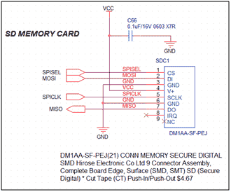
This tutorial was specifically written around the microcontroller I am using, which is the ST upsd3334D microcontroller. Since it is fundamentally an 8052, you should be able to adapt this tutorial to your specific microcontroller; however, some of the Special Function Registers will probably be different. The upsd3334D is unique in that it is not only an 8052, but also a CPLD(Complex Programmable Logic Device) in the same part. The 8052 portion of the part is 3.3v and the CPLD portion is 5.0v. The hardware interface to the SD card is simple. The signals can connect directly to the 3.3v pins on the 8052, but I added 30 ohm resistors to reduce signal bounce.


MMC Connection to controller

In this tutorial, the SD memory card is attached to the 3.3v section of the micro, so no voltage shifting is necessary.

MMC Connection to controller

Remember: The SD memory card has a limited voltage range, so ALL signals to and from it are a maximum of 3.3v. If you connect 5.0v signals to the SD memory card, you might damage it.


Additionally, I am using the Keil development PK51 suite, which consists of the IDE (Integrated Development Environment), the C51 compiler, the AX51 assembler, and the LX51 link-loader. The version is 8.17a, but I believe any version should work.

If you would like to read more about CPLD’s, you can visit this link: http://en.wikipedia.org/wiki/CPLD

If you would like to read more about the processor I am using, you can visit this link: http://www.keil.com/dd/chip/3639.htm

MMC SD Card Interfacing

Introduction to Chan’s Library : MMC SD Card interfacing

►Introduction to Chan’s Library

First of all, if you haven’t downloaded Chan’s source code, you should do this first. You can get from him at this link:

http://elm-chan.org/fsw/ff/00index_e.html

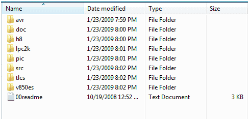
When you unzip this file, use the default directories and you will end up with a directory structure like this:

elm chan FAT16 files


Chan has included examples for a variety of processors. The basic set of routines are found in the src subdirectory. As he notes in his readme file, the files included here are:

FileDescription
ff.hCommon include file for FatFs and application module.
ff.cFatFs Module
tff.hCommon include file for Tiny-FatFs and application module.
tff.cTiny-FatFs module.
diskio.hCommon include file for (Tiny-)FatFs and disk I/O module.
diskio.cSkeleton of low level disk I/O module.
integer.hAlternative type definitions for integer variables.

Chan also states that

chan wrote ...
the low level disk I/O module is not included in this archive because the FatFs/Tiny-FatFs module is only a generic file system layer and not dependent on any specific storage device. You have to provide a low level disk I/O module that is written to control your storage device.

That is the intent behind this tutorial – to show you how to write the low level disk I/O module so the file system layer can work properly.

Friday, 4 January 2013

Programming 8051 Microcontroller

►Programming 8051 Microcontroller

►8051 Assembly Program for 4x4 Keypad Matrix

CODE:
keyport equ P2                  ;Keypad port connected here
col1 equ P2.0                   ;Column 1
col2 equ P2.1                   ;Column 2
col3 equ P2.2                   ;Column 3
col4 equ P2.3                   ;Column 4

keyval equ 30H                  ;To store key number
pressed bit 0H                  ;Flag

key_init:
        mov keyport,#0FH        ;Make rows as o/p and col as i/p
        ret

get_key:
        mov keyval,#0           ;reset the number
        mov keyport,#7FH        ;make Row1 low
        acall read_col          ;read columns

        jb pressed, done        ;check if flag is set

        mov keyval,#4           ;if not then read next row
        mov keyport,#0BFH       ;make Row2 low
        acall read_col          ;read columns

        jb pressed, done        ;check if flag is set

        mov keyval,#8           ;if not then read next row
        mov keyport,#0DFH       ;make row3 low
        acall read_col          ;read columns

        jb pressed, done        ;check if flag is set

        mov keyval,#12          ;if not read row4
        mov keyport,#0EFH       ;make row4 low
        acall read_col          ;read columns

done:
        ret

read_col:                       ;read columns routine
        clr pressed             ;reset the flag

        jb col1, nextcol        ;check if first key is pressed
        jnb col1,$              ;if yes then wait for key release      
        setb pressed            ;set the flag
        ret

nextcol:                        ;read col2
        jb col2, nextcol1       ;check if second key is pressed
        jnb col2,$              ;if yes then wait for key release
        inc keyval              ;its key number 2
        setb pressed            ;set the flag
        ret

nextcol1:                       ;read col3
        jb col3, nextcol2       ;check if third key is pressed
        jnb col3,$              ;if yes then wait for key release
        inc keyval              ;its key 3
        inc keyval
        setb pressed            ;set the flag
        ret

nextcol2:                       ;read column 4
        jb col4, exit           ;check if fourth key pressed
        jnb col4,$              ;if yes then wait for key release
        inc keyval              ;its key 4
        inc keyval
        inc keyval
        setb pressed            ;set the flag
        ret

exit:                           ;if no key is pressed
        clr pressed             ;clr the flag
        clr keyval              ;reset the number
        ret

        end


►C Program for 4x4 Keypad Matrix

CODE:
#include <AT89X51.H>    //Include file for 8051
#define keyport P2      //keypad connected to P2
#define col1 P2_0       //column 1
#define col2 P2_1       //column 2
#define col3 P2_2       //column 3
#define col4 P2_3       //column 4
#define TRUE 1          //some defines
#define FALSE 0

/*
+---------------------------------------+
| Prototype: void key_init(void);       |
| Return Type: void                     |
| Arguments: None                       |
| Description: Initialize ports and     |
|              Keypad.                  |
+---------------------------------------+
*/

void key_init(){
        keyport &=0x0F; //make Rows as o/p and cols are i/p
}

/*
+-----------------------------------------------+
| Prototype: unsigned char get_key(void);       |
| Return Type: unsigned char                    |
| Arguments: None                               |
| Description: To read key from the keypad      |
+-----------------------------------------------+
*/

unsigned char get_key(){
        unsigned char i,k,key=0;
        k=1;
        for(i=0;i<4;i++){               //loop for 4 rows
                keyport &=~(0x80>>i);   //to make rows low 1 by 1
                        if(!col1){      //check if key1 is pressed
                                key = k+0;      //set key number
                                while(!col1);   //wait for release
                                return key;     //return key number
                        }
                        if(!col2){      //check if key2 is pressed
                                key = k+1;      //set key number
                                while(!col2);   //wait for release
                                return key;     //return key number
                        }
                        if(!col3){      //check if key3 is pressed
                                key = k+2;      //set key number
                                while(!col3);   //wait for release
                                return key;     //return key number
                        }
                        if(!col4){      //check if key4 is pressed
                                key = k+3;      //set key number
                                while(!col4);   //wait for release
                                return key;     //return key number
                        }
                k+=4;                   //next row key number
                keyport |= 0x80>>i;     //make the row high again
        }
        return FALSE;                   //return false if no key pressed
}


Example of how to use the above functions is given here.